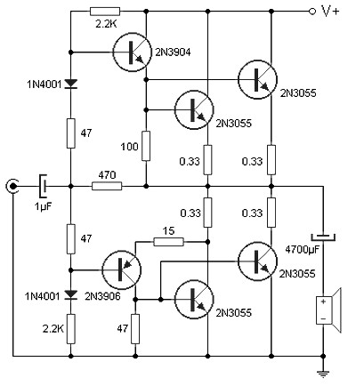

What do you suggest? How can I protect the output transistors and what is the possible cause of this behaviour? Shorting the output immediately kills transistors ~70% of the time, which I want to prevent. I cannot repeatedly apply the load and prevent frying them. The inductor does not resolve the problem but clears irregularites on the scope as expected. BTW after working and blowing some trannies, I put a random inductor to limit instantenous current, here it is for reference The scope result is with this inductor in place, and from one of the initial tries before frying a transistor. The limiting seems to work nice to me - voltage drops to about 10V after 300us. Here is a capture on the scope The first channel is the voltage drop across the ~0.24 ohm shunt resistor and second channel is the output voltage after applying the load. I'm using 4 3055s and believe that it must be within spec even if I use a single transistor - with current limiting set at ~3 amps. This should draw about 9 amps when not current limited. The major problem I'm having is that I keep frying at least one of the output transistors when testing with a 2.2Ohm load at 20V output. Schematic One thing that I've found so far is the power rating of R7 should be high as it is dissipating power at high output levels. I only had one like that.Hi, I'm working on building a current limited bench power supply at. My guess is they found out about the gooey feet a long time ago and changed the vendor. There were many slight variations over 40 years.

Some extra study on the 723 is also useful. RB site has lots of docs about these supplies. I only bought one new, all the others were donated basket cases. I have 5 of these supplies and use a RS20 for a test jig. Compare case temps with a IR thermometer. If the gain of one of the pass transistors exceeds the rest, it will hog the current and short or blow leaving the others to do the work. The only device rating in danger for 3771 or 5686 is the junction temp (unless they are fakes) and there is always resistance from the junction to the outside world. I provided a large slow computer fan to the heatsink because I use a VS35 as low as 4 or 5 volts, and this will increase the dissipation on the heatsink far greater than at 13.8v for the same current.
#2n3055 pass transistor schematic driver#
If you make the driver do more dissipation, you need more heatsink or airflow there, Replacing 2n3055 with 2n5686 (with same gain) works just fine but they get just as hot unless you provide airflow or a bigger heatsink. But the same dissipation is happening for whatever output is happening. If I could get 2n5686 for a good price in bulk, It would replace all the other replacements. If there is too much load for the chip supply or the Pass supply, or the capacitance, or driver or pass transistors saturate, there is ripple modulation. After changing the gains around you have to re-adjust these with testing of the threshold with a variable load and scope. Short circuit protection set point involves R4, R3, Rx on pin 2 and also involves R1,Rx.


 0 kommentar(er)
